A while back I bought Wainlux JL3 laser engraver. The feature list of the machine was acceptable at the time I bought it.
- Wireless control
- Large engraving size (at least for me) – 410 X 370mm
- Aluminum extrusions for frame
- 30W diode laser (not sure if it’s accurate as it might be overdrived to acheave this power)
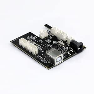
- 32-bit motherboard
Reason I wanted to flash grbl at all
After using it for a while I have come to some conclusions about this device and original proprietary firmware and app combination. And here are the things that I don’t like about it
- App seems really unstable as sometimes the conversion from image to the commands for laser image gets offset and duplicated resulting in wasted matereal and power
- wireless mode is useless as mobile app is limited and janky
- the machine is noisy… the machine tries to hold the motors in position, but while doing so the motors make this weird high pitch noise
- proprietary firmware isn’t compatible with LaserGRBL or LightBurn that has much more configuration options
- IT’S DANGEROUS – when you turn on the machine it turns on the laser at 10% power by default, and this is reset after restart of the control application and control board
What options are there to fix this?
After seeing how this machine failed to do its jobs on multiple occasions I figured it is time for a change, but what are the options. There are two options on how to do this. One of the options is to buy a new controller that supports grbl and flash it to it and the second one is get grbl working on Wainlux motherboard, but I would loose wireless capability that doesn’t work as expected by default (without putting in extra effort).
As I am cheap and I know programming I thought that it was easier for me to spend time and reverse what connects to where and try to flash stm32 port of grbl
Where did everything go wrong?
Long story short I did manage to get the stm32 port to somewhat work with the pinout of the Wainlux motherboard, but I had some issues with laser PWM and homing sequence. It just looked like timers that control PWM are glitching or not working at all in laser PWM case.
I focused on laser not working for a while and the thing I figured out is that laser PWM pin(that is located on PB0 on this board) has only 2 timers you can assign it to generate PWM. One is TIM1 on channel 2N and other one is TIM3 channel 3. The GRBL port used TIM1 channel 1 for laser PWM generation, and obviously it didn’t work. Then I changed the code so that it would use TIM1 Channel 2N for PWM generation, but then the chip became unstable. It started to send random serial messages with positions and other stuff to the control software and after a while it crashed. After that I tried TIM3 Channel 3 for PWM generation, but still there was no PWM on the pin. So I tried to create a sample project that just generates the PWM on the PB0 output and after fiddling around for a bit I got it working, but the grbl port still didn’t work.
At this point in time I have spent at least 40 hours troubleshooting this thing and I want to use the laser engraver… So it’s official I give up. I will buy standard 32 bit controller after I get back from vacation.
Conslusion
To be honest I recently found out that Wainlux has grbl firmware for JL3 that they will provide if you ask them politely for it. I also think that I could fix this if I would invest lots of extra time. The main reason why this is taking me so long and why I can’t troubleshoot this fast is lack of experience with the STM32 platform. I should get back to this later, but since I need reliable platform fast I will order grbl controller from Aliexpress or some other site that offers china electronics.
2 responses to “Why I gave up on reverse engineering Wainlux JL3 motherboard so I can use GRBL with it”
You have failed with your project because with partial remap/Alternative Function, of moving TM0_CH2N to B0, it also moves some stuff to UART1, that have to be explicitly commented out in HAL. I had same problem and after fiddling with HAL for other pins – GRBL on JL1 is solid.
I have compiled fully working firmware, including custom homing, firmware and there is effort to get GRBLHAL adapted to it.
https://forum.lightburnsoftware.com/t/firmware-for-jl1-board/74877
https://github.com/LsrSal/DEE_JL1
Thanks for the explanation, Sal. As I said in the article I have almost no hands-on experience with the STM32 platform. I will check my attempt source code and try flashing your firmware on the JL1 board.